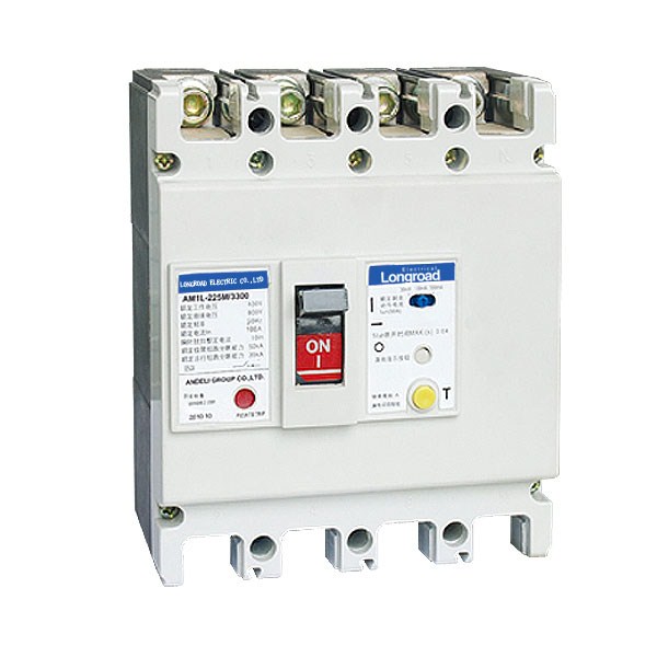
AM1L Series Earth Leakage Circuit Breaker
Product Detail:
1.Application
AM1L series earth leakage circuit breaker are one of the new type earth leakage breakers which have been developed by the company using international advanced design and manufacturing technology. Suitable for a line of AC50Hz/60Hz, rated voltage up to 400V, rated current 16A to 630A. and is acted as infrequent changeover of circuit or infrequent starting of motor. The breaker has overload, short-circuit and under-voltage protective function, which can protect the circuit and the power equipment against damage, meanwhile, it can provide protection to these fire dangers that caused by these long-time existed grounding fault that can not be detected by the over-current protection.
This breaker can be installed vertically(upright) or horizontally(transverse).
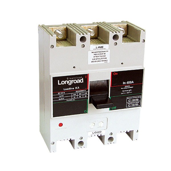
Wiring of the breaker can not be in adverse direction, that means power supply line must be connected to terminal 1,3 and 5,and the load line connected to terminal 2,4 and 6.
The rated residual operating current I△n and the maximum breaking time can be adjusted on site according to practical condition.
The leakage protection module still can work normally when the phase voltage reduce to 50V. It has the same overall size with the AM1 series breakers, which make the installation more exchangeable.
The breakers are suitable for isolation, its symbol are:
The breakers comply with the demands of the following standards:
IEC60947-1 and GB/T 14048.1 General
IEC60947-2 and GB 14048.2 Low voltage breakers
IEC60947-4 and GB 14048.4 Contactors and motor starters
IEC60947-5.1 and GB 14048.5 Electrical equipments of electromechanical control circuit
2. Main Technical Specifications
Type | AM1L-100 | AM1L-225 | AM1L-400 | AM1L-630 | ||||||||
Frame Current Inm(A) | 100 | 225 | 400 | 630 | ||||||||
Rated current In(A) | (10)16,20,25,32,40,50,63,80,100 | 100,125,160,180,200,225 | 225,250,315,350,400 | 400,500,630 | ||||||||
Pole Number | 3 | 4 | 3 | 4 | 3 | 4 | 3 | 4 | ||||
Rated Insulation Voltage Ui(V) | AC800 | |||||||||||
Rated Working voltage Ue(V) | AC 400V | |||||||||||
Rated impulse with stand voltage Uimp(V) | 8000 | |||||||||||
Arc-over Distance(mm) | >50 | |||||||||||
Breaking capacity grade | M | H | M | H | M | M | ||||||
Limiting short-circuit breaking capacity lcu (kA) | AC400V | 50 | 85 | 50 | 50 | 85 | 50 | 65 | 65 | |||
Service short-circuit breaking capacity lcs(kA) | AC400V | 35 | 50 | 35 | 35 | 50 | 35 | 42 | 42 | |||
Rated residual operating current I △ n(mA) | Non-delay type | 100/300/500 | ||||||||||
Delay type | 100/300/500 | 300/500/1000 | ||||||||||
Rated residual nonoperatingcurrent I △no(mA) | 1/2 I △ n | |||||||||||
Operation performance (time) | Electrified | 1500 | 1000 | 1000 | 1000 | |||||||
Unelectrified | 8500 | 7000 | 4000 | 4000 | ||||||||
Note: According to the pole number of product, it calssifies three and four poles. The neutral pole (N-Pole) of the four-poles products has four types:
Type A: N-pole without over-current release unit, it has been connected all the time, not closing and opening with the other three poles.
Type B: N-pole without over-current release unit, which closing and opening with the other three poles.
Type C: N-pole fixed with over-current release unit, which closing and opening with the other three poles.
Type D: N-pole fixed with over-current release unit, it has been connected all the time, not closing and opening with the other three poles.
1. The limiting breaking and arc-over distance includes horizontal and vertical installation.
2. If the three-pole breaker of this series is connected with three phase load, the load can not have neutral line, otherwise the breaker will have fault action.
3. If the three-pole breaker of this series is connected with single phase load, the phase line willbe connected to the left pole, and the neutral line is connected to the right pole, the middle pole is blanket
3. Protection Characteristic
The thermal release of the breaker has again-time-limit property; the electromagnetic release is inst. Operation, its property see table 2(for distribution),table 3 (motor protection).
Rated current of Release(A) | Thermal release (ambient temperature+40oC) | Electromagnetic release operating current(A) | |
1.05In(cold state ) non-operating time (h) | 1.03In(hot state) acting time (h) | ||
10 ≤ In ≤ 63 | 1 | 1 | 10In±20% |
63 ≤ In ≤ 125 | 2 | 2 | |
125 ≤ In ≤ 630 | 2 | 2 | 5In±20% 10In±20% |
Rated current of Release | Thermal release (ambient temperature +40oC) | Electromagnetic Release operating current(A) | |||
1.0In (cold state) non-operating time(h) | 1.20In(hot state) acting time(h) | 1.50In(thermal state) operating time | 7.2In(cold state) operating time | ||
10≤In≤400 | 2 | 2 | 8min | 6s < TP ≤ 20S | 12In±20% |
4. Residual current operating time of earth leakage circuit breaker
4.1 Non-delay type operation characteristics see table 4(I△n≤30mA should be Non- delay type)
Rated current | I△n | 2I△n | 5I△na | 10I△n | |
Non-delay type | Max.breaking time(s) | 0.3 | 0.15 | 0.04 | 0.04 |
Note: ato I△n≤30mA earth leakage circuit breaker, 0.25A can instead of 5I△n According toa, adopt 0.25A, then 10 I△n is 0.5A.
4.2 Delay type operation characteristics see table 5
Limiting non-driven time of delay type earth leakage circuit breaker according to 2l△n,operation characteristics see table 5
Delay time (s) | Max. breaking time(s) at I△n | Limiting non-driven time (s) at 2 I△n | Max. breaking time(s) | Max. breaking time(s) at 5I△n | Max. breaking time(s) at 10 I△n |
0.1 | 0.4 | 0.06 | 0.2 | 0.15 | 0.15 |
0.2 | 0.5 | 0.06 | 0.2 | 0.15 | 0.15 |
0.3 | 0.6 | 0.1 | 0.4 | 0.3 | - |
0.4 | 0.7 | 0.2 | 0.5 | 0.4 | - |
0.5 | 0.8 | 0.3 | 0.6 | 0.5 | - |
0.6 | 0.9 | 0.4 | 0.7 | 0.6 | - |
0.7 | 1.0 | 0.5 | 0.8 | 0.7 | - |
5 .Accessories of circuit breaker
5.1 The external accessories of the breaker
Motor-driven operation device
1) Wiring diagram of type CDM electromagnetic operation device(fitting AM1L-100,225) see thefollowing drawing (wiring diagram of the external accessories of the breaker in the dotted frame)

2) Wiring diagram of type CD motor-driven operation device (fitting AM1L-400I630) see belows(wiring diagram of the external accessories of the breaker in the dotted frame)
Code description: SB1 SB2 stand for push button.(provided by users themselves) Number "1" "2" "3" stand for number of wiring terminals.Voltage rating: AC50Hz 230V 400V, DC 220V

Code description: SB1 SB2 stand for push button. (provided by users themselves) "X" stands for line connection terminalsVoltage rating: AC50Hz 230V 400V; DC220V
Rotary handle operation device The mechanism is used in moulded case circuit breaker to operate the draw-out panel. Powerdistribution panel and supply box outside the panel by turning the handle,and to ensure thedoor of panel would not be openned when the breaker being on. The hand-drive mechanism can be equiped with two types of operation one is "A" modelsquare handle , the other is "B" model round handle.
5.2 The internal accessories of the breaker
5.2.1 Release pattern and accessories code see following table

Release patternand accessories code | Name\Type | AM1L- 100,225 | AM1L-400 | AM1L-630 |
200, 300 | No accessories | 200: Magnetic release (only short circuit protection) | ||
208, 308 | Alarm contact |
|
|
|
210, 310 | Shunt release |
|
|
|
220, 320 | Auxiliary contact |
|
|
|
230, 330 | Under-voltage release |
|
|
|
228, 328 | Auxiliary contact,Alarm contact |
|
|
|


5.2.2 The technical parameter and functions of the accessories
Accessory | Rated operating voltage (V) | |||
AC50Hz | DC | |||
Shunt Release Us | 220(230) | 380(400) | 110 | 220 |
Under-voltage Release Us | 220(230) | 380(400) | ||
Auxiliary contact and Alarm contact: Auxiliary contact is as some as Alarm contact , the techni-cal parameter see following table
Rated heating current Ith (A) | Rated operating current Ie(A) | Suited Frame Inm(A) | |
AC380V | DC220V | ||
3 | 0.3 | 0.15 | 100, 225 |
3 | 0.4 | 0.15 | 400, 630 |
Accessories name | Function | Wiring connection diagram |
Alarm contact | Indicate circuit breaker at tripping | 
|
Auxiliary contact | Indicate circuit breaker at opening or closing | 
|
Shunt release | The shunt release should make the breaker trip reliably when theoperatiopn voltage is 70%-110% of rated control voltage | 
|
Under-voltage | When Ue is 35%-70% of the rated control voltage, the under voltagerelease should make the breaker trip correctlyWhen Ue is 85%-110% of the rated control voltage, the under voltagerelease should make the breaker closeIn case of Ue less than 35%of the rated control voltage should preventthe breaker from closing | 
|


Type | Outline dimensions | Installation dimensions | ||||||||||||||||||||
Back panel connection | Back panel connection | Plug-in | ||||||||||||||||||||
W | L | H | W1 | L1 | L2 | H1 | H2 | L3 | H3 | D | L4 | L5 | H4 | H5 | H6 | C | D | D1 | A | B | d | |
AM1L-100M,H/3P | 92 | 150 | 92 | 60 | 200 | 200 | 132 | 110 | 28.5 | 90 | 93 | 168 | 92 | 50 | 64 | 76 | 60 | 56 | 6.5 | 30 | 129 | 4.5 |
AM1L-100M,H/4P | 122 | 150 | 92 | 90 | 200 | 200 | 132 | 104 | 28.5 | 90 | 93 | 168 | 92 | 50 | 64 | 76 | 60 | 56 | 6.5 | 30 | 129 | 4.5 |
AM1L-225M,H/3P | 107 | 165 | 90 | 70 | 265 | 265 | 144 | 110 | 24 | 93 | 100 | 183 | 94 | 50 | 71.5 | 86.5 | 90 | 54 | 6.5 | 35 | 126 | 5.5 |
AM1L-225M,H/4P | 142 | 165 | 103 | 105 | 265 | 265 | 144 | 127 | 24 | 93 | 100 | 183 | 94 | 50 | 710.5 | 86.5 | 70 | 54 | 6.5 | 35 | 126 | 5.5 |
AM1L-400M,H/3P | 150 | 257 | 106.5 | 96 | 441 | 441 | 224 | 146.5 | 38 | 164 | 108.5 | 279 | - | 60 | 83.5 | 106.5 | 105 | 129 | 8.5 | 44 | 194 | 7 |
AM1L-400M,H/4P | 198 | 257 | 106.5 | 144 | 441 | 441 | 224 | 146.5 | 38 | 164 | 108.5 | 279 | - | 60 | 83.5 | 106.5 | 70 | 129 | 8.5 | 44 | 194 | 7 |
AM1L-630M,H/3P | 210 | 280 | 115.5 | 145 | 480 | 480 | 243 | 155 | 45.3 | 158 | 84 | 296 | - | 61 | 97 | 148 | 140 | 143 | 10 | 70 | 243 | 7 |
AM1L-630M,H/4P | 280 | 280 | 115.5 | 210 | 480 | 480 | 243 | 155 | 45.5 | 158 | 84 | 296 | - | 61 | 97 | 148 | 210 | 143 | 10 | 70 | 243 | 7 |
Relateproduct
-
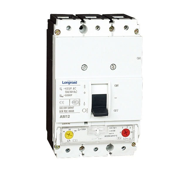
AM12 Series Moulded Case Circuit Breaker
-
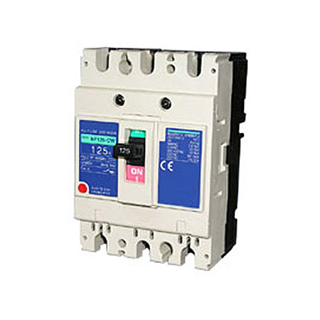
AM11-CW Series Moulded Case Circuit Breakers
-
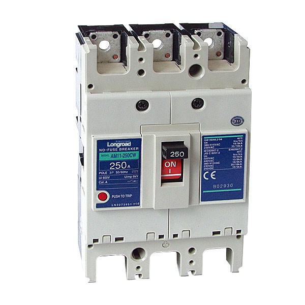
AM11 Series Moulded Case Circuit Breaker
-
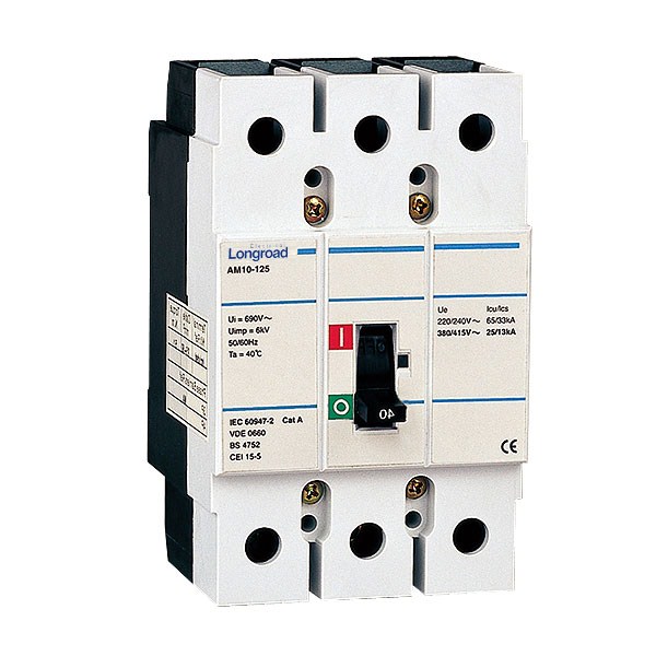
AM10 Series Moulded Case Circuit Breaker
-
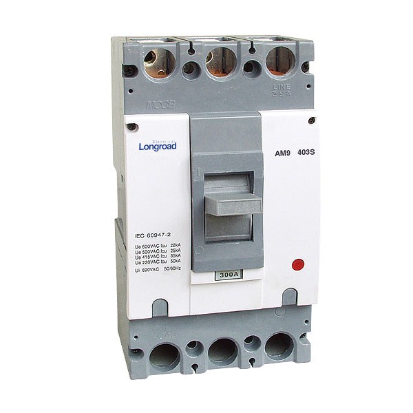
AM9 Series Moulded Case Circuit Breaker
-
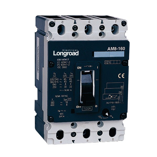
AM8 Series Moulded Case Circuit Breakers
-
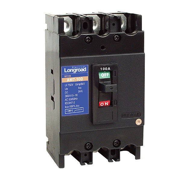
AM7 Series Moulded Case Circuit Breaker
-
AM6 Series Moulded Case Circuit Breaker